DISASSEMBLY of the Model M-125-3MN/-3MP3 Fialka:
The following section describes and displays the Disassembly of the
Model M-125-3MN/-3MP3 Fialka. The Fialka Menu above gives access to
descriptions and photographs of the Model M-125-MN Fialka, the different rotor
sets and wiring and rotation data, the 24 Volt DC power supply and its cables
and the metal cover and ...
This excellent German language link provides additional information about
the Fialka: http://people.freenet.de/SASundChiffrierdienst/seiten/fialka.html
The model M-125-3MN/-3MP3 Fialka is much more complex than the M-125-MN version with a number of major differences. The M-125-MN is very similar to the M-125-3MP3 and M-125-3MP2 Fialkas with the only apparent differences being in the keyboards.
Differences between the Model M-125-MN and Model M-125-3MN/-3MP3
Fialkas:
The M-125-3MN/-3MP3 has many complex features that are not included in the
M-125-MN. These include:
1. A multilingual keyboard.
2. A mechanical switch along the right side of the keyboard
that modifies keyboard function.
3. A 3-position lever on the back of the Fialka that modifies paper tape
punch operation.
4. A large matrix switch that alters the wiring of the programming matrix and
therefore the effect of the programming cards.
5. A rotary switch located under the base of the Fialka.
6. A position on the input rotor switch that stops rotation of the rotors and
character counting as characters are typed in.
7. An extended copyholder.
All of these features will be shown and described in the following page:
Descriptions, Photographs, and Disassembly of the
M-125-3MN/-3MP3 Fialka:
Note: The pictures show a model M-125-3MP2 Fialka which is very similar to a
model M-125-3MN and M-125-MP3.
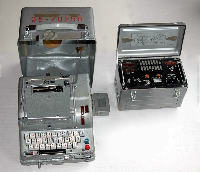
External Appearance and Features:
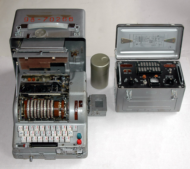
An overall view of the M-125-3MN Fialka with cover open showing accessories.
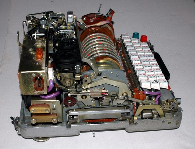
A view of the left side of the M-125-3MN Fialka before disassembly.
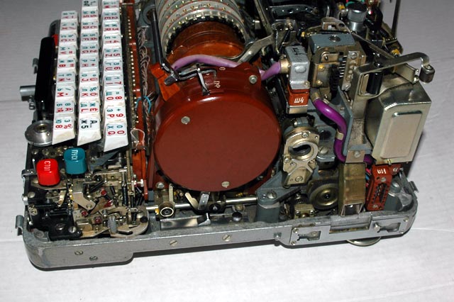
A view of the right side of the M-125-3MN Fialka before disassembly.
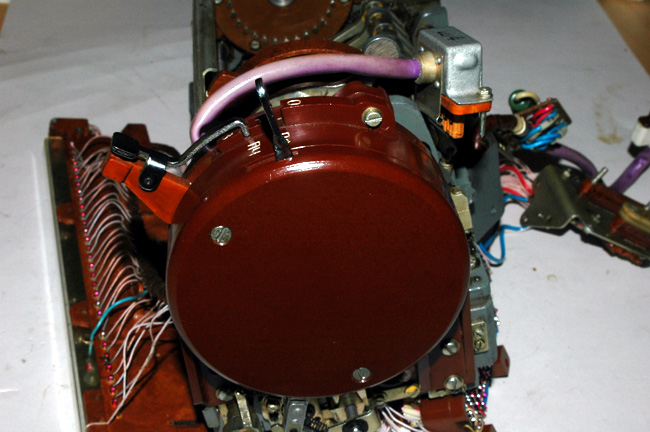
A view of the back of the M-125-3MN Fialka before disassembly.
A closer view of the back of
the M-125-3MN Fialka. The motor mechanism is about to
be removed.
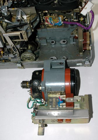
A view of the back of the M-125-3MN Fialka after the motor mechanism has
been unscrewed and removed.
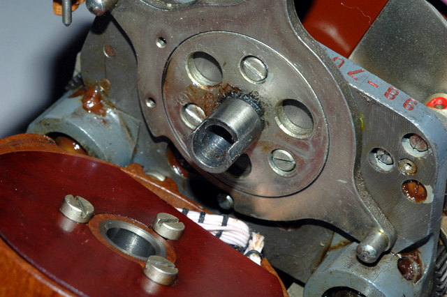
A closer view of the back of
the M-125-3MN Fialka showing the mounting
position and mounting screw locations
of the motor mechanism.
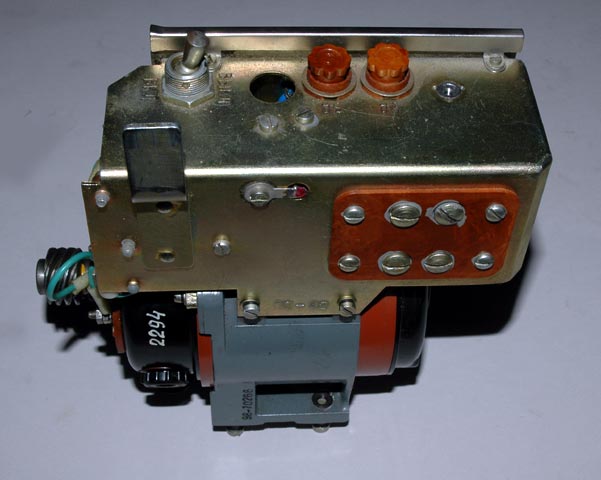
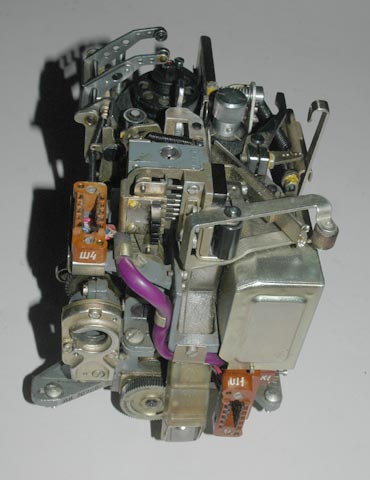
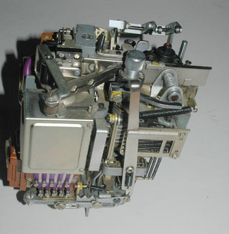
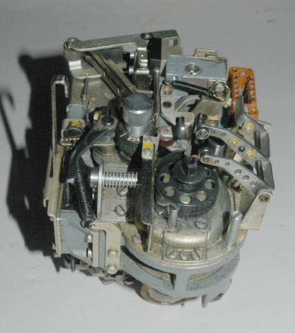
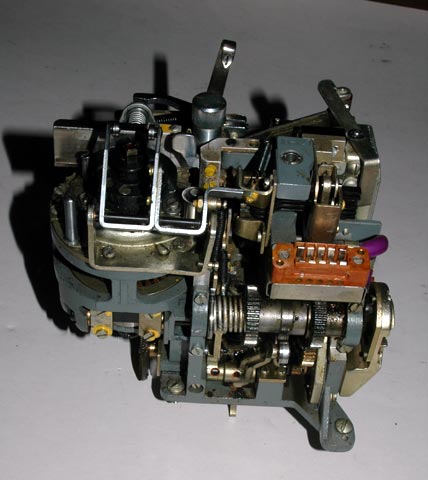
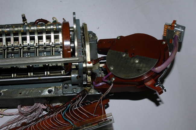
A closer view of the back of the motor mechanism.
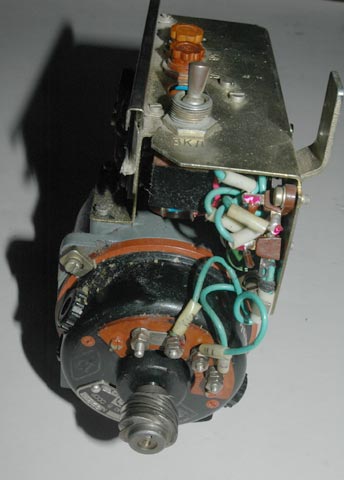
A closer view of the front of the motor mechanism.
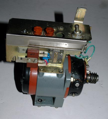
A closer view of the right side of the motor mechanism.
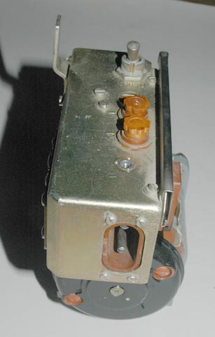
A closer view of the left side of the motor mechanism.

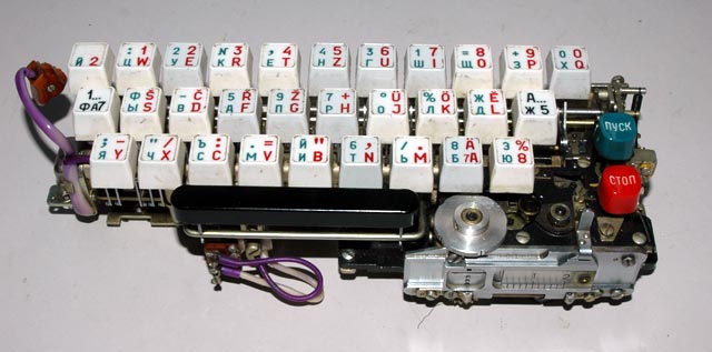
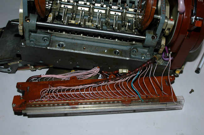
The Keyboard after it has been unscrewed and moved foward from the base of
the M-125-3MN Fialka. The brown rocker switches on the rotor assembly are
mechanically activated by small pins that extend from the keyboard whenever a
character is typed.
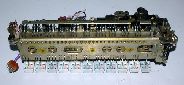
The Keyboard after it has been unscrewed from the base of the m-125-3MN
Fialka and rotated forward. The row of small round holes along the edge
of the keyboard contain the small pins that extend from the keyboard whenever
a character is typed. These pins press against the rocker switches on the
rotor assembly that can be seen in the background.
The Keyboard being rotated backwards away from the viewer. The paper tape
reader mechanism can be seen on the lower right.
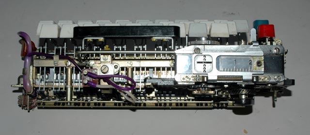
The Keyboard being rotated backwards away
from the viewer. The paper tape reader mechanism is on the right.
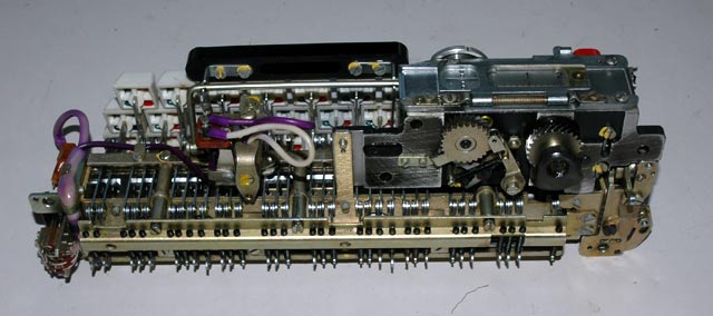
The Keyboard being rotated backwards away from the viewer. The gears that
drive the paper tape reader mechanism can be seen on the right. They engage a
motor-driven gear on the base of the Fialka.
The Keyboard being rotated backwards away from the viewer. In this view
you can see the row of small round holes that contain the pins that activate
the rocker switches on the rotor assembly when a keyboard key is pressed.
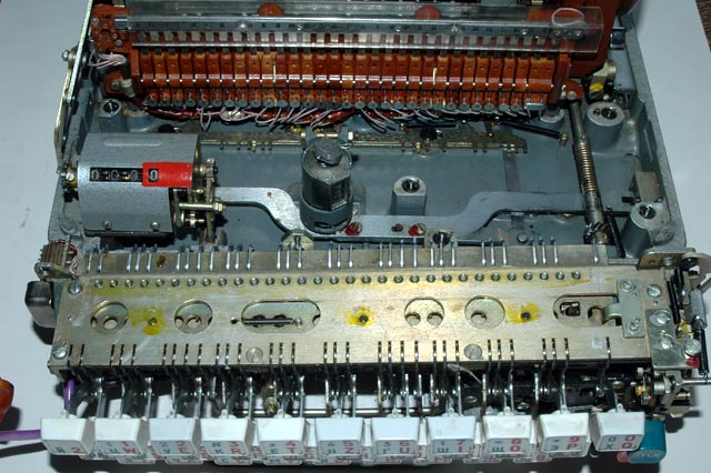
The base plate after removal of the keyboard
showing the character counter, the sealed secure character counter and the
rocker switches that are mechanically activated when a keyboard key is
pressed.
A closer view of the rocker switches that are mechanically activated when
a keyboard key is pressed.
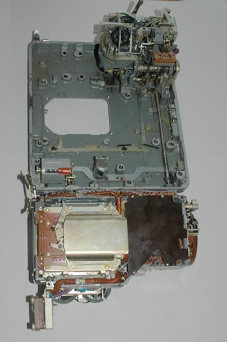
The base plate of the M-125-3MN Fialka after removal of the motor module,
the keyboard, and the rotor mechanism. This view also shows the top of the
rotor mechanism
The base plate of the M-125-3MN Fialka after removal of the motor module,
the keyboard, and the rotor mechanism. This view also shows the keyboard
activated switches on the front of the rotor mechanism
The base plate of the M-125-3MN Fialka after removal of the motor module,
the keyboard, and the rotor mechanism. This view also shows the bottom of the
rotor mechanism where the punched card reader is located.
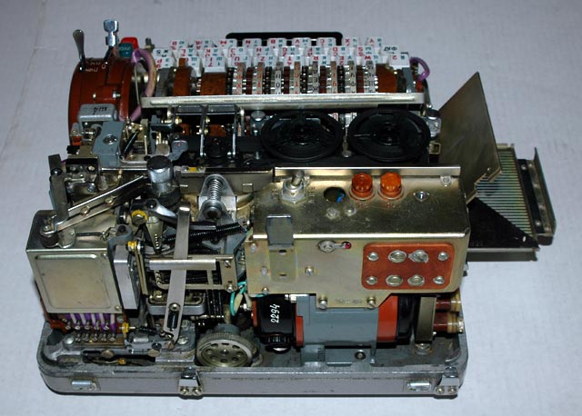
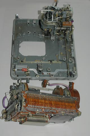
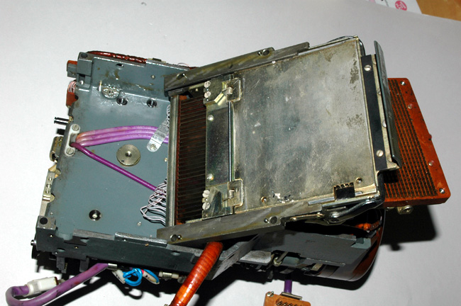
The base plate of the M-125-3MN Fialka before removal of the paper tape
printer and punch mechanism located in the right rear corner.
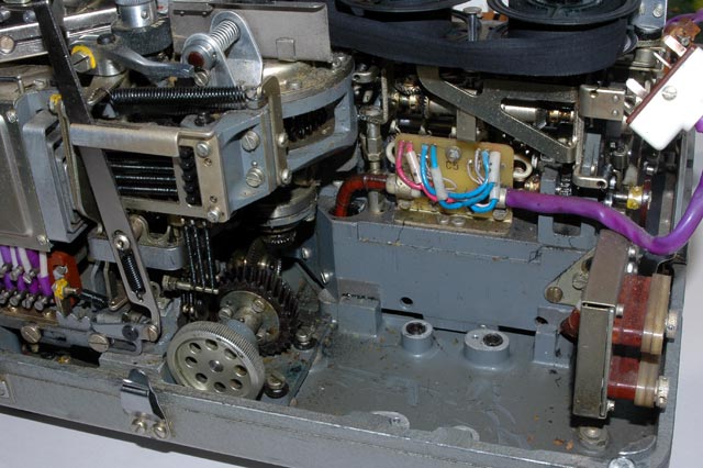
The base plate of the M-125-3MN Fialka after removal of the paper tape
printer and punch mechanism. It is shown in the right rear corner of this
photograph. The previously removed electric motor mechanism is in the left
rear corner of the picture.
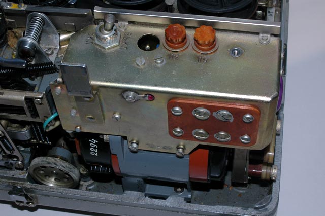
A right side view of the paper tape printer and
punch mechanism.
A back view of the paper tape printer and
punch mechanism.
A left side view of the paper tape printer and
punch mechanism.
A front view of the paper tape printer and
punch mechanism.
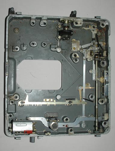
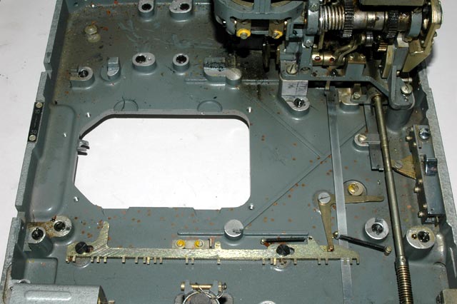
A top view of the base plate with all modules removed.
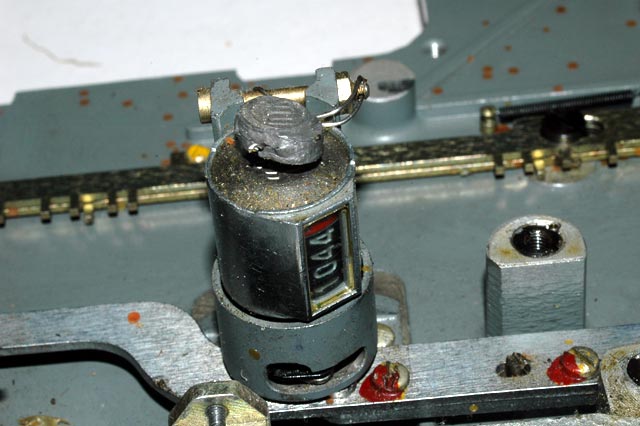
A top view of front of the base plate showing
a close view of the sealed secure character counter.
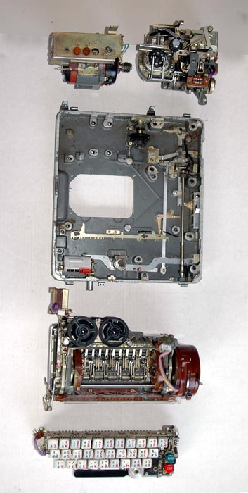
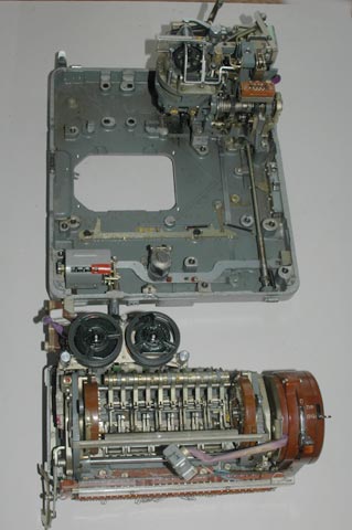
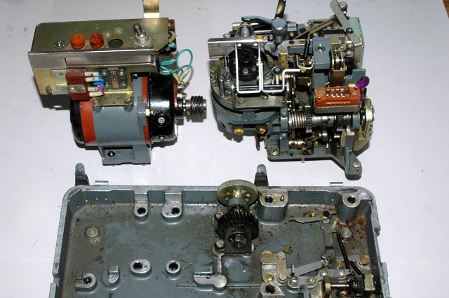
A top view of the base plate showing all of the individual modular
components after removal. The Motor module is in the top left corner. The
paper tape printer and punch module is in the top right of the picture. The
rotor mechanism module is below the base plate. The keyboard is below it.
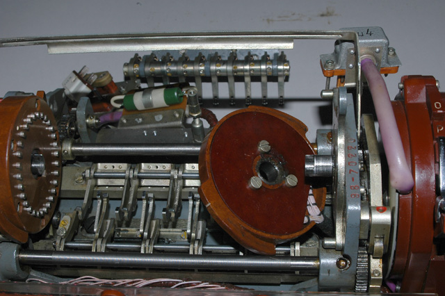
A top view of the rotor mechanism showing the
brown reflector on the left and the brown input wheel on the right.
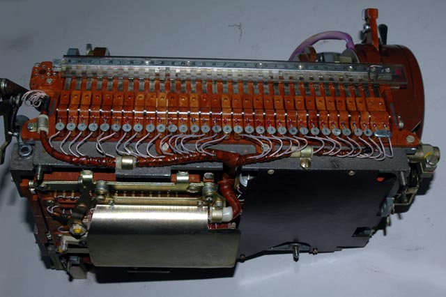
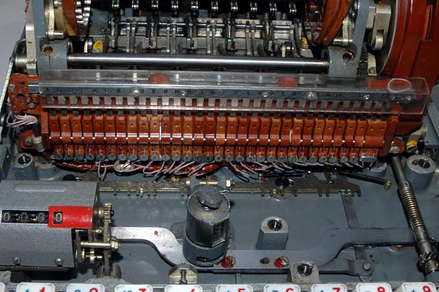
A front view of the rotor mechanism showing the
keyboard activated rocker switches.
In this view, keyboard activated rocker switch module has been unscrewed
and moved away from the rotor mechanism to show the normally-closed rocker
switch connections and the partly unbundled wiring.

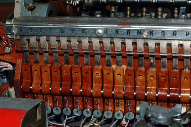
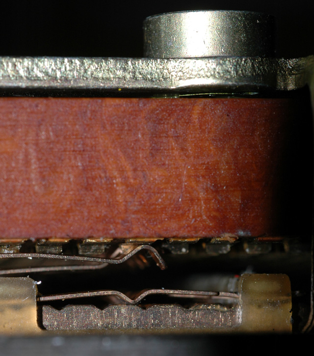
A close view of the rocker switches showing the normally-open contacts on
the top and the normally-closed contacts on the bottom.
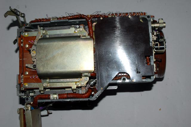
A bottom view of the rotor mechanism showing the black plastic cover over
the internal circuits on the right and the metal cover over the slide switch
on the left. The two position slide switch lies under the metal cover and
switches many circuits simultaneously. This switch is part of the circuit
that changes languages and most of the input wiring to this switch comes from
the keyboard and goes to the card reader mechanism that lies under it.
A closer view of the two position multi-contact slide switch on the bottom
of the rotor mechanism that switches many circuits simultaneously.
A still closer view of the two position multi-contact slide switch on the
bottom of the rotor mechanism that switches many circuits simultaneously. It
has been unscrewed from the card reader mechanism that lies under it.
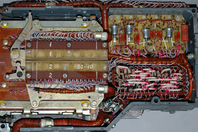
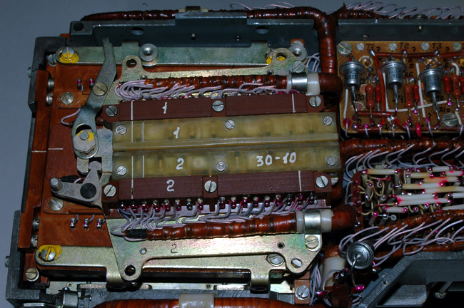
The two position multi-contact slide switch on the bottom of the rotor
mechanism that switches many circuits simultaneously has now been disassembled
on one side to show its internal contacts. Most of the pins on the white
plastic sliding contact bar (Marked '1') are connected to one adjacent pin.
When the bar moves, these contacts slide along the contacts on the stationary
brown bar (Marked '1') and connect adjacent pins on this bar which are
connected to the wiring. Note that much of the wiring has been unbundled to
help in tracing the connections.
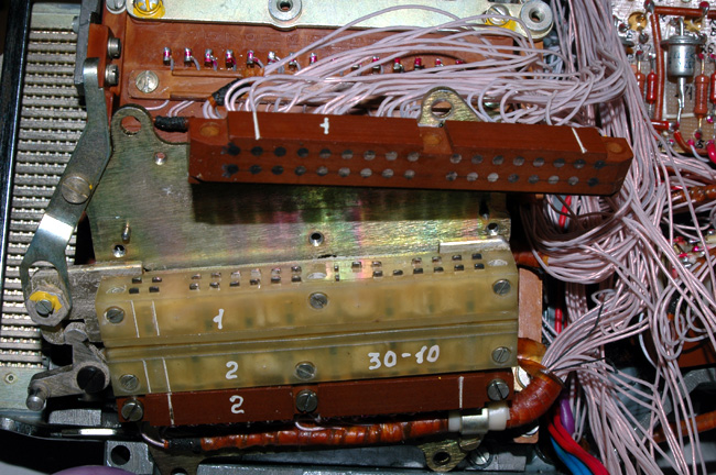
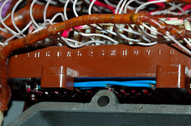
A bottom view of the rotor mechanism after the the multi-position slide
switch has been swung back to reveal the connections on the punched card
reader mechanism.
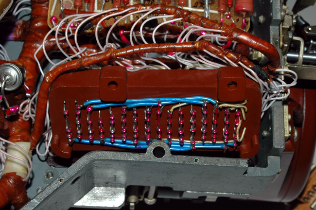
A bottom view of the rotor mechanism showing a closer view of the
connections on the punched card reader mechanism. This view shows the
contacts numbered 1-30 that are connected directly to the 'common' or 'rocker'
connections of the keyboard-activated rocker switches numbered 1-30. If you
look closely, you can see the numbers.
The order of the connections is not simple so it is given below. If you count
the 30 keyboard-activated rocker switches from left to right as being numbers
1 - 30, the following is the sequence of numbered contacts on this punched
card reader that are connected to the normally-open contacts of the rocker
switches: The first number is the keyboard-activated rocker switch number and
the second number is the number on the punched card reader mechanism.
1-
17, 2-25, 3-30, 4-14, 5-26, 6-21, 7-6, 8-19, 9-1, 10-15, 11-29, 12-20, 13-4,
14-28, 15-24, 16-2, 17-22, 18-23, 19-18, 20-12, 21-7, 22-5, 23-27, 24-8, 25-
10, 26-9, 27-16, 28-13, 29-11, 30-3.
For example: The leftmost rocker switch (number 1) has its common connection
connected to contact 17 of the punched card reader mechanism. The next rocker
switch to the right (number 2) is connected to contact 25 on the punched card
reader mechanism, and so on.
As you can see, no wiring is color-coded and it is all bundled and wrapped
together making tracing the circuit very difficult. As the disassembly
progresses, you will see that I have removed the bundling and wrapping and
freed the individual wires for visual tracing.
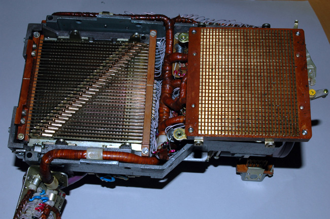
In this view, the bottom of the punched card reader mechanism that contains the 30 connections described above has been unscrewed and swung to to the right to show all of the individual contact pins. These pins on the right are each connected to a contact bar that runs from top to bottom of this picture. These bars are perpendicular to the bars on the lower part of the card reader mechanism.
Each of these perpendicular bars is therefore connected to the 30
horizontal bars shown on the left by the sliding contacts that are mounted on
each of the bars on the left. These sliding contacts are slid along the bars
to a predetermined position as the punched card is slid into the mechanism by
the punched card carrier. In this picture, the sliding bars on the left are
shown in the default position that is created by the use of the triangular
metal insert that is contained in the punched card mechanism and that
positions the sliding contacts when no punched card is used.
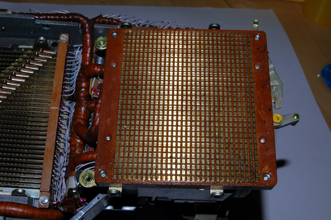
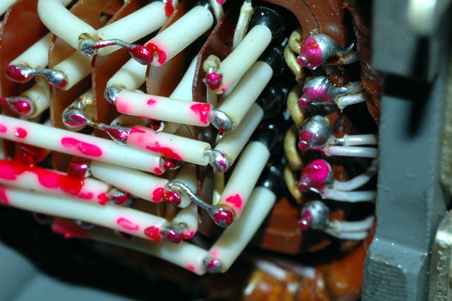
A closer view of the bottom of the punched card reader mechanism that contains the 30 connections described above with wires that come from the keyboard and the switch. These 30 connections go to the 30 bars that run up and down in this picture. Each of these bars provides 30 pins that are seen in this view.
These pins are connected to the horizontal 30 bars shown on the left by the
sliding contacts that are mounted on each of the bars on the left. These
sliding contacts are slid along the bars to a predetermined position as the
punched card is slid into the mechanism by the punched card carrier. In this
picture, the sliding bars on the left are shown in the default position that
is created by the use of the triangular metal insert that is contained in the
punched card mechanism and that positions the sliding contacts when no punched
card is used.
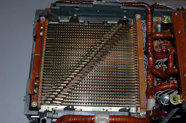
A closer view of the punched card reader mechanism showing the sliding
contacts that are mounted on each of the bars on the left. These sliding
contacts are slid along the bars to a predetermined position as the punched
card is slid into the mechanism by the punched card carrier. In this picture,
the sliding bars on the left are shown in the default position that is created
by the use of the triangular metal insert that is contained in the punched
card mechanism and that positions the sliding contacts when no punched card is
used.
In this view the punched card reader mechanism has been unscrewed from the
bottom of the rotor mechanism and the wiring has been unbundled and unwrapped
to allow visual tracing of the wiring.
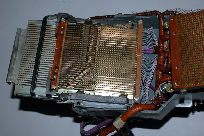
This view shows the sliding contacts that are connected to and slide along
each of the 30 bars. They have been slid along the bars as the punched card
carrier was slid into the mechanism. In this picture, the punched card
carrier was slid only part way into the card reader.

This is a very close view of the sliding contacts that are connected to and
slide along each of the 30 bars. The bars can be seen on the bottom of
the picture and the pins that the sliding contacts make contact with are in
the top of the picture.
This is an even closer view of the sliding contacts that are connected to
and slide along each of the 30 bars. The bars can be seen on the bottom of
the picture and the pins that the sliding contacts make contact with are in
the top of the picture.
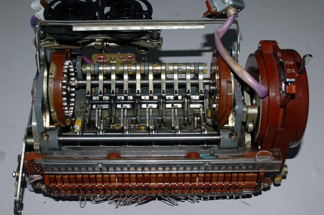
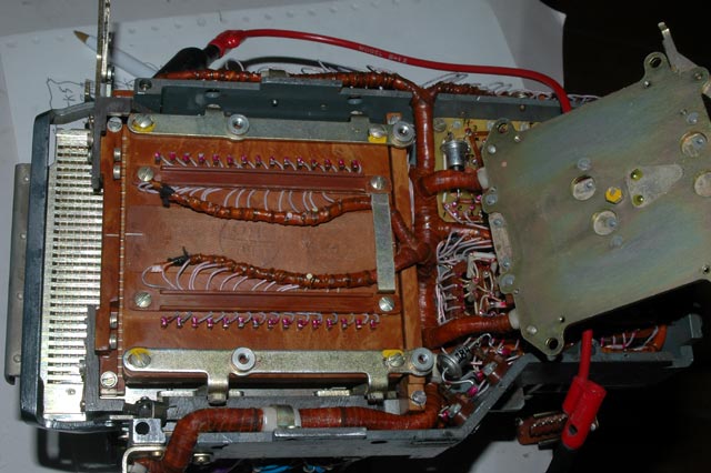
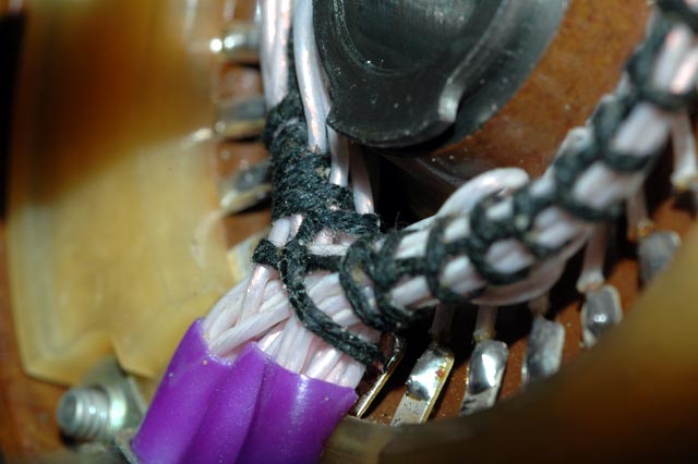
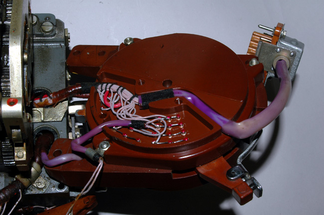
In this view the entire punched card reader mechanism has been swung to
the right to reveal the wiring coming from the reflector and from a switch.
The three LIGHT purple wires contain bundles of wires coming from the
reflector. The DARK purple wire contains a bundle of wires coming from a
rotary switch that closes every time the rotor mechanism is activated to
rotate the rotors.
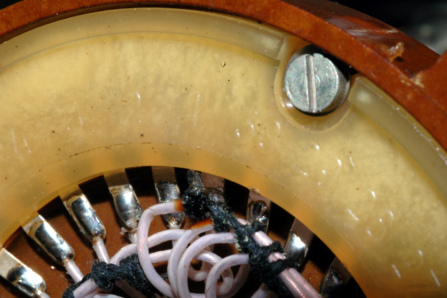
In this view the cover over the swing-up door of the punched card
reader mechanism on the right can be seen in the closed position.
This door opens when the punched card carrier is slid out of the Fialka and
it allows the punched cards to be inserted. It can be seen in the open
position in the next picture.
In this view the cover over the swing-up door of the punched card reader
mechanism has been removed to show the door in the open position. This door
opens when the punched card carrier is slid out of the Fialka and it allows
the punched cards to be inserted. The default triangular metal insert is
shown in place that allows positioning of the sliders into a default diagonal
pattern when no punched card is inserted.
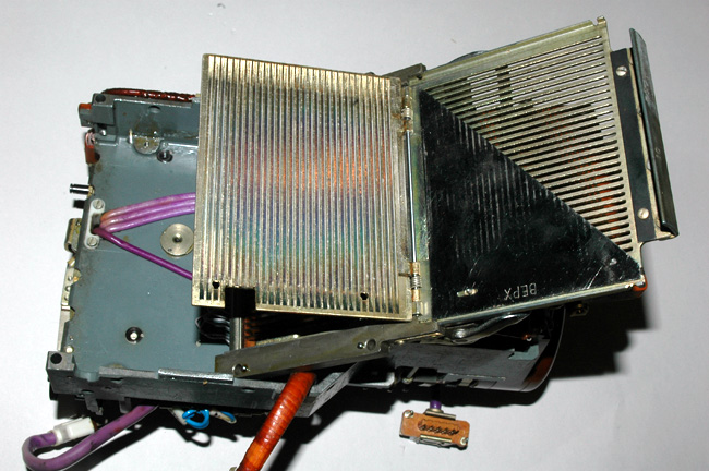
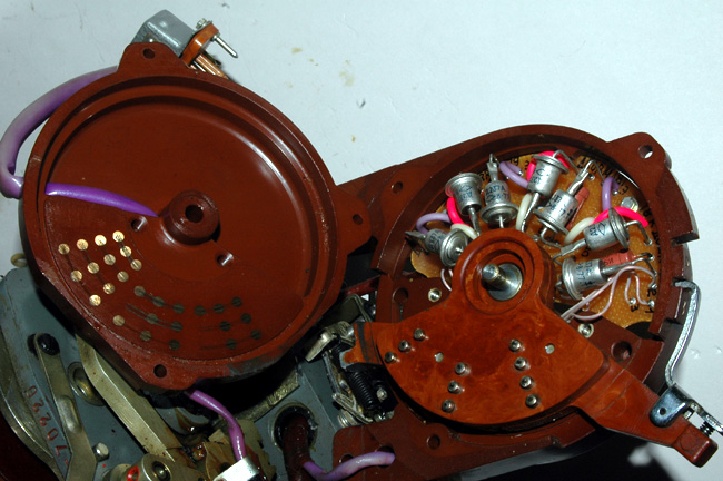
A bottom view of the rotor mechanism after the
cover over the paper tape punch driver circuits
(top right) and the diode matrix (bottom right) has been removed.
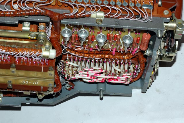
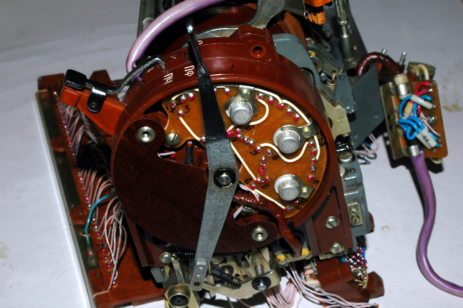
A closer view of the paper tape punch driver
circuits (top right) and the diode matrix (bottom right).
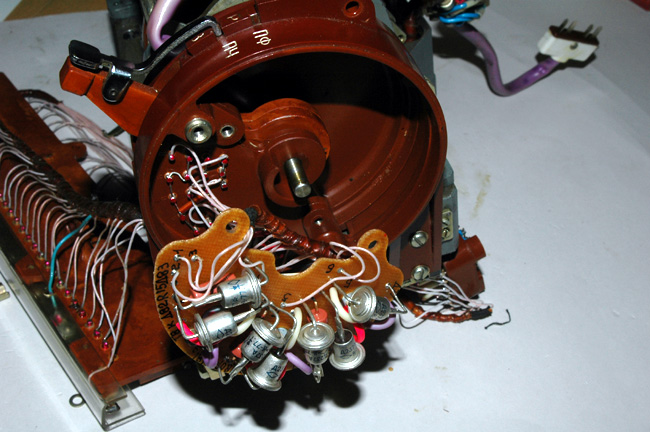
A view of the paper tape punch driver circuits. The driver circuit board
has been unscrewed and tipped forward to allow viewing of the other side of
the circuit board.
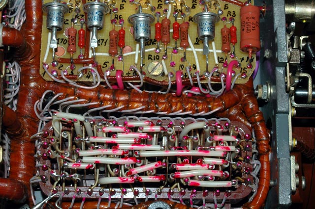
A closer view of the diode matrix (bottom).
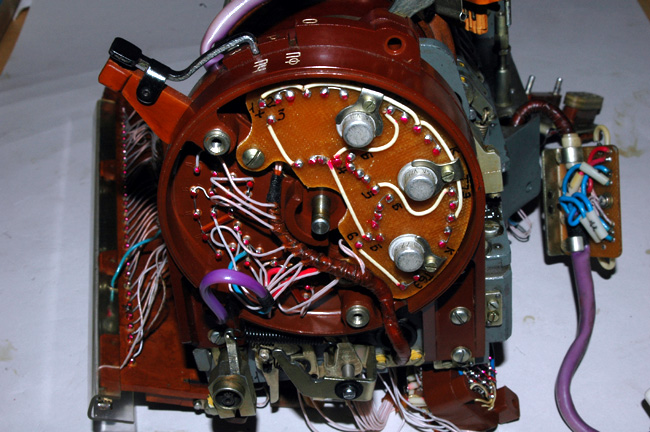
A closer view of the diode matrix showing the
very complex wiring and partially hidden diodes.
A closer view of the diode matrix showing the
very complex wiring and partially hidden diodes.
The diodes can be seen as the black cylinders
in this picture.
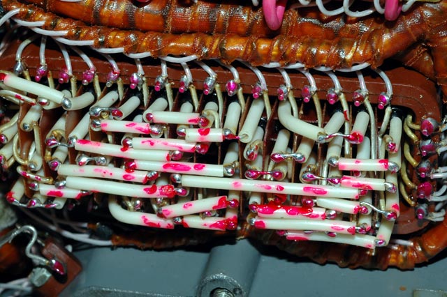
A view of the bottom of the diode matrix showing the
very complex wiring.
A view of one the two input sides (long sides) of the diode matrix showing
the very complex wiring. If you look closely, you can see the letters of the
keyboard's normally-closed contacts that connect to each point on the diode
matrix.
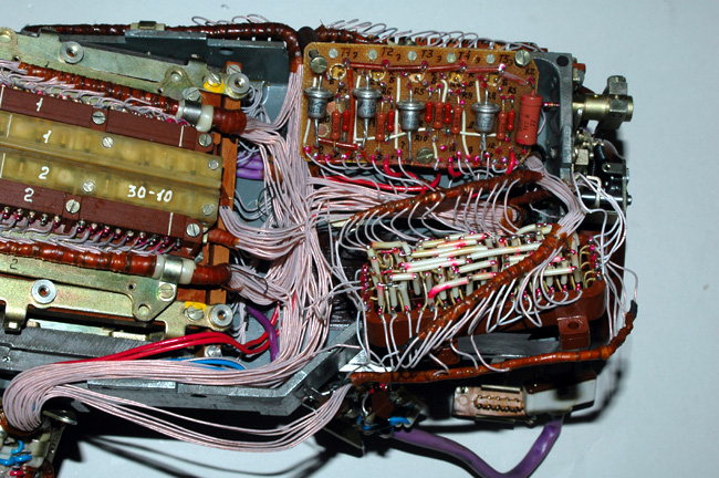
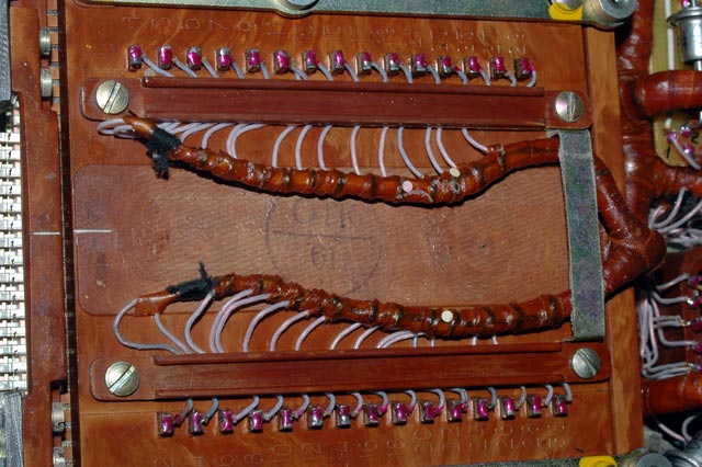
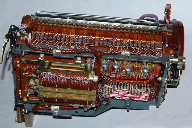
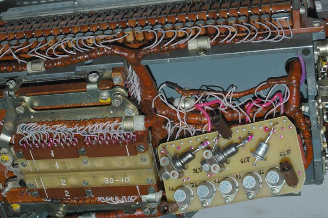
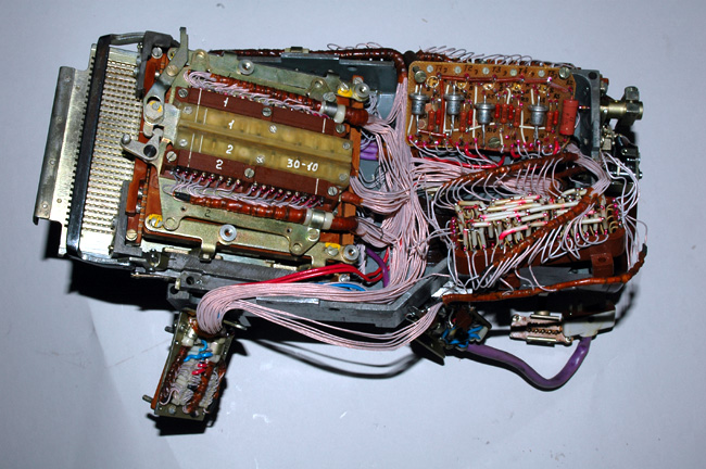
An overview of the switch and card reader on the left and the diode matrix
and printer driver circuit board on the right after the bundling and wrapping
of the wires has been removed to facilitate tracing the individual wires.
Another overview of the switch and card reader on the left and the diode
matrix and printer driver circuit board on the right with the bundling and
wrapping of the wires removed to facilitate tracing the individual wires.
The rotor assembly after the detent levers have been removed to allow the
brown reflector on the left and the brown input wheel on the right to be slid
inward and removed from their shafts for disassembly.
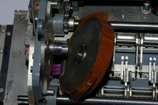
The reflector assembly after being slid off it's axle. Note the easily
removable cover over the wiring.
The reflector assembly after the easily removable cover has been removed
from its position over the wiring.
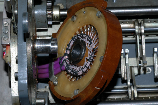
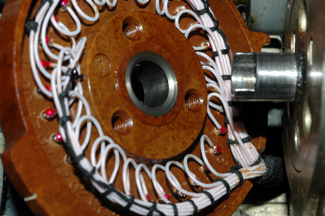
A close view of the three bundles of wires that are connected to the
reflector.
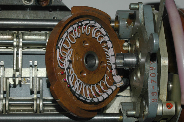
A close view of the wiring of the reflector. If you look closely, you can
see that every connection is numbered from 1 to 30. The number 1 is
straight up and numbers 2, 3, 4, etc. run back and around the reflector.
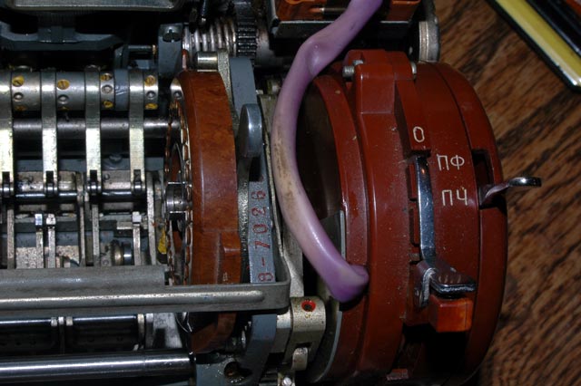
A close view of the input wheel and switch assembly on the right end of the
rotor stack. Note that the serial number of the Fialka is stamped into the
frame of the rotor mechanism.
The input wheel assembly after being slid off it's axle. Note the easily
removable cover over the wiring.
The cover has been removed from the input wheel to allow access to the
wiring.
A closer view of the wiring of the input wheel. Note that each connection
has a number from 1 to 30 adjacent to it. These numbers start with 1 at the
top and increase as you move back and around the wheel.
This is the axle and rotor locking lever for the input wheel. Moving the
lever forward moves the metal pins against the cams on the brown input wheel.
This the input wheel inwards to compress the rotor stack.
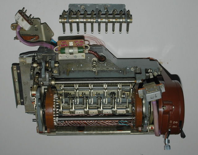
A view of the switch assembly on the right end of the rotor stack.
Another view of the switch assembly on the right end of the rotor stack
after the cover has been removed. The mechanical switch lever and printer
driver ciruit board are now visible.
Another view of the switch assembly on the right
end of the rotor stack after the cover and mechanical switch lever have been
removed. The printer driver ciruit board and part of the internal switching
circuits are now visible.
Another view of the switch assembly on the right
end of the rotor stack after the cover and mechanical switch lever have been
removed. The printer driver ciruit board has been unscrewed and pulled out
to show the circuit components.
The other side (Left side) of the switch assembly on the right end of the
rotor stack. Note the metal plate that covers the switch connections.
A closer view of the switch connnections on the other side (Left side)
of the switch assembly on the right end of the rotor stack. The metal plate
has been removed to show the connections.
A closer view of the switch contacts on the other side (Left side)
of the switch assembly on the right end of the rotor stack after the
switch mechanism has been disassembled to show the internal wiper contacts.
NOTE: I AM ALWAYS INTERESTED IN PHOTOGRAPHING OR BUYING VERY UNUSUAL ENIGMA-RELATED MATERIALS, PARTS, EARLY COMPUTERS, AND TELEGRAPH KEYS !
Professor Thomas B. Perera
Montclair State University
COPYRIGHT NOTICE: (Copyright (c) 2005: Prof. Tom Perera Ph. D.)
Although all the pictures and text are copyrighted, you may use any of them
for your own personal applications including public lectures and
demonstrations, publications and websites as long as you mention the
www.w1tp.com/enigma Museum. If you plan to offer them for sale to the public
in any form, you must email me for permission which I will generally grant as
long as you mention my museum: http://w1tp.com/enigma. My email address is
given at the bottom of this page. Some of the material may require contacting
other copyright owners for commercial use and I will inform you by email.
Please also see the disclaimer of warranty.